|
DIGITAL INPUTS Up to 6 SPST contacts can be wired to terminals 07-12. Status is reported on indicatori LED [F]. Internal power supply available at terminal 06. Analog inputs (terminal 02-05) can be used as additional digital inputs. Debounce time setting for each input in the range 1 second to 18 hours |
|
|
INPUT voltage |
3 ... 9 VCC |
|
INPUT current |
2 mA @ 3,3V |
|
output voltage |
3,3 VDC AT TERMINAL 06 |
|
|
|
|
Inputs I1-I6 can operate also as a pulse or time counter. SPST contacts, magnetic reeds, hall sensors or electronic switches can be used. |
|
|
PULSE WIDTH |
> 20 ms |
|
FREQUENCY |
< 25 Hz |
|
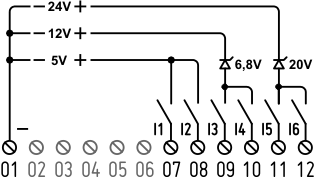
If switches are supplied by an external power supply, negative terminal must be connected to terminal 01. A zener diode can provide an easy solution to keep input voltage in the 9Vdc range. The following figure shows some possible wiring diagram. |
|
|
|
|
|
|
|
|
|
|
A WIEGAND reader can be connected to digital inputs I1 (data 0, terminal 07) and I2 (data 1, terminal 08). Led indicators are illuminated when data line is connected. Negative (GND) to terminal 01. Led 1 and 2 are illuminated when associated data line is connected. |
|
|
|
|
|
CON When inputs are supplied by external source, negative is connected to terminal 01, voltage must be kept within 9 VDC. External power supply for inputs and optional wiegand reader must meet SELV circuits requirements according to EN/IEC 62368. |
|